Changing Value Field Properties
Value fields allow the user to import or export numerical or signal input to and from the component. Value fields include the following numerical sub-types:
Real
Integer
Logical
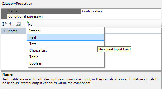
To add a new value field to a category page, select the category in the Categories tree and then select Real, Integer or Logical within the Add Parameter Field drop list button in the tool bar:
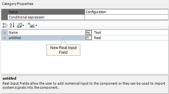
A new value field will appear:
Value field properties can be adjusted directly on the category page. Left-click on the [+] box to expand the value field tree node.
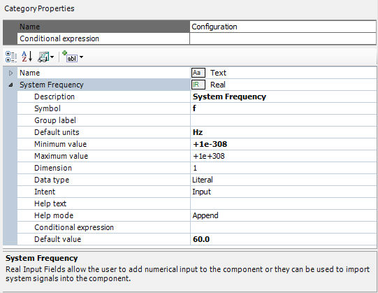
The properties available are described as follows:
Description: Enter a caption to act as the visible title of the value field.
Symbol: Enter a symbolic name for the value field, which will be used as a variable name when addressing this field within code. Note that this name must be compatible with standard Fortran naming conventions (i.e. it must begin with a non-numeric character, do not include spaces, etc.).
Group Label: Use this field to organize the display of the input parameters in the actual component parameter dialog. All parameter fields that possess the same group name will be grouped together under the group name heading.
Default Units: Add a unit (if any) to represent the Target Unit related to this Field. See Unit System for more details.
Minimum / Maximum Value: Enter the maximum and minimum value limits. If you are unsure of what these limits should be, or limits are not required, simply enter -1e+038 and 1e+038 respectively. If value outside this range is entered, PSCAD will provide a warning in the Build or Runtime Message Panes upon compilation.
Dimension: Real and Integer type parameters may be defined as single-dimension arrays. Simply enter the dimension of the array here. Note that non-scalar parameters (i.e. dimension > 1) must be set as Data Type | Variable.
Data Type: Select Literal, Constant or Variable. The selection of data type is very important. Please see the following section entitled Value Field Data Types for a complete description of each.
Intent: Select whether or not this parameter is to function as an input or an output parameter. The intent setting is important to ensure well formed Fortran code is generated for this component when the project is built.
Help Text: Enter a brief statement describing the field. This text will be displayed on the actual input parameter dialog for the component.
Help Mode: Select Append or Overwrite. If Overwrite is selected, only the help text will appear at the bottom of the dialog when the user selects this parameter. If Append is selected, then the prompt text will be appended to the other parameter attribute information displayed.
Conditional Expression: Enter a conditional statement to indicate under what input conditions the input field is to be enabled. See Conditional Statements, Layers & Filters for more details.
Default Value: Use this field to add a value, which will appear as the default value in the input field parameter display. Assume that a user who is not familiar with this component might simply accept your default value for lack of a better value. So, do your best to enter an appropriate value here.
Value fields can be subdivided into two types: Real and Integer. These data types are quite familiar in programming languages and can be readily defined. In PSCAD, Real, Integer and Logical type value fields can be further categorized into three sub-types: Literal, Constant and Variable.
PSCAD versions prior to X4 allowed only type Literal and Variable value fields. Seasoned users will remember the use of the Allow Signal Names option in the Value Field dialog: By default, all value fields were Literal, but could be made Variable by selecting this option.
As a direct by-product of the multiple instance module (MIM) feature, a third input field sub-type was created and dubbed a Constant. A Constant type input field is a hybrid of sorts in that it possesses key properties of the other two data types. For example, a Constant type field cannot be modified during runtime like a Variable, but can accept the name of a previously defined signal, or an actual number (Literal).
A brief definition and example is given below for each data type:
Literal: Literal type value fields will accept only fixed, numeric values. For example: 23, 657.29, -33.8, or -1 are all valid inputs. Literals are defined at build time, and remain fixed throughout the simulation.
Constant: Constant type value fields will accept only fixed input. However, unlike a Literal type, it will also accept a signal name as its value. The signal value must be from a source that is fixed (non-variable). For example: freq, my_signal, out2, as well as all the examples given for a Literal type above. Constants are defined at build time, and remain fixed throughout the simulation.
Variable: Variable type value fields accept both numeric and non-numeric input. Input values may remain fixed, or they can vary throughout the simulation. This value type is equivalent to having the Allow Signal Names option enabled in PSCAD versions previous to X4.
See Multiple Instance Modules for more details on using Constant type value fields.