Build or Compilation Messaging
PSCAD does not include a real time error manager, so in order to generate and view any warning or error feedback you must first compile and build your project. Error messaging is displayed in the Build Messages pane. This classification can be very helpful in determining just what the problem is, and how to fix it.
As discussed in the Build and Runtime Message Panes topic, this table includes messages sourced from the building or compilation of the project (build). The build messages pane will also display messages involving transmission line and cable solving, as well as other, general informational messages.
The build or compilation process as you can imagine, is a complicated one. However, it can be simplified a bit by further sub-dividing it into steps:
Building Source and Data Files for Simulation: In this first step of the build process, PSCAD collects all of the module definitions in the project and compiles them. The result of this compilation is the creation of source (i.e. Fortran (*.f) files) and Data (*.dta) files. If one or more problems exist in any module, an error or warning message will be issued. PSCAD will complete this step by compiling all modules flagged for compilation, regardless if errors are detected in any single module: Compilation will not continue to the next step however.
Creating Map File: Once all of the modules have been built, their respective local nodes and subsystems must be linked together globally – this is performed during the creation of the project Map (*.map) file. If there are illegal issues with connectivity between modules, or something of the like, pertinent error and warning messages will appear here.
Creating Make File: The Make (*.mak) file is written as an instructional file for the Fortran compiler. Any problems during this process will be displayed here.
Solving Transmission Segments: The final process before the simulation executable file is produced is to solve all transmission line and cables in the project. For each transmission segment, PSCAD produces either a Transmission Line Input (*.tli) or a Cable Input (*.cli) file and then calls the Line Constants Program (LCP) to solve the segment. If a problem occurs during the process of constructing the input file (ex. Checks segment logic failure), or the LCP solve fails, an error or warning message will be displayed here.
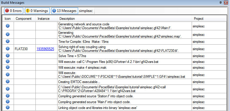
The following image illustrates the messages for the steps described above in the Output Window:
Obviously there was no problem building the simpleac project above. Any error messages that do occur will appear under their respective categories.
Upon the successful completion of the build process, the runtime process will begin. Runtime messages are streamed directly from EMTDC to PSCAD into a separate pane called the Runtime Messages pane. These messages are related directly to the runtime process and contain information such as: Messages related to the running of the executable file, EMTDC software copyright information and time summary information.
These messages are very important, and include; file read errors, matrix manipulation, and any other type of problem arising from the initialization of the run. When initially debugging and refining a project, users should continually consult the messages displayed here.
There are a large number of possible error and warning messages that can be generated and displayed in the Output Window. A message source can originate directly from the PSCAD or EMTDC applications, or may be generated by individual components. Most of these messages however, will never occur if a project is judiciously constructed in the first place.
The following descriptions outline the most common occurring messages.
This warning is issued if PSCAD detects an open electrical circuit connection on a component - usually caused by an electrical node that is not connected to anything.
If an open circuit connection is indeed what you wish to accomplish, the suggested method to deal with this warning is to connect a large resistance (approximately 1 MW) to ground at the node. This will ensure numerical stability and will have negligable affect on the simulation results.
A key has not been properly defined or does not exist in the component data.
<name> is the name of the text input field.
This warning is issued if PSCAD detects a REAL signal being sent to an input expecting an INTEGER. PSCAD will automatically convert the REAL signal value to the nearest integer, hence the warning.
<name> is the name of the signal.
This error is issued if PSCAD detects a signal of the same name being generated from more than one source. This error is most commonly caused when component instances with defined internal output variables are copied, hence duplicating the internal output variable.
<name> is the name of the signal. <instance_name> is the name of the component.
This error is issued if PSCAD detects that a signal of dimension <dim_1> is being sent to an input expecting a signal of dimension <dim_2>. This error commonly occurs with the power electronic switch components, which expect a 2-dimensional input gate signal when set for interpolation.
<name> is the name of the signal.
This error is issued if PSCAD detects an array signal type mismatch. For example, if a data signal array was defined as type INTEGER and the user attempted to tap off a single element with the Data Signal Array Tap component set to type REAL (or vice-versa); or, if an array of type REAL is input into a component, where the external input Connection in question is defined as an INTEGER array.
<name> is the name of the signal.
This error is related to the use of the Breakout component: Ground components cannot be directly connected to Breakout terminals. The Breakout is designed specifically for mapping multiple connections on the scalar side to a single array. Since Ground nodes cannot be mapped, the compiler will issue this warning. The suggested work around is to use a Current Meter as a series element between the Breakout terminal and ground. See the section entitled Valid Connections in the Breakout component online help for more details.
<Node> is the name of the Breakout reference node connected to ground.
This error is related to the use of the Breakout component: The nodes on the 3-phase side of this component are not actual electrical nodes, but references that will assume the node number to which they are connected. This error is posted if these reference nodes are shorted (i.e. electrically connected together). Each node on the 3-phase side of the Breakout component must be unique. See the section entitled Valid Connections in the Breakout component online help for more details.
<Node> is the name of the Breakout connection which is shorted.
This error is related to the use of the Breakout component: The nodes on the 3-phase side of this component are not actual electrical nodes, but references that will assume the node number to which they are connected. A special condition that cannot be referenced is referred to as an 'unbalanced' condition, where the imbalance refers to electrical nodes, not actual impedance. The basic rule to remember here is that all branches on the 3-phase side must include at least one series impedance. See the section entitled Valid Connections in the Breakout component online help for more details.
<Node> is the name of the Breakout connection which is shorted.